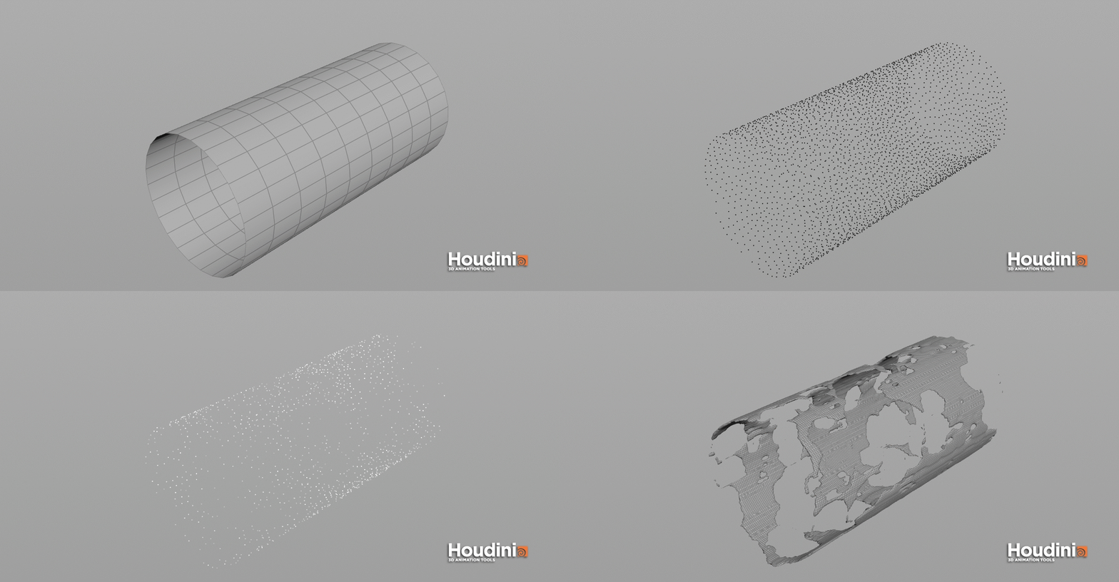
But no, that's not the real reason we have spare inputs. The Big Sell of for-loops when they first arrived is that they could be multi-threaded. Points describe the position of the junctions of our meshes. The GPU however works with vertices and needs 3 vertices to render a triangle even if the points appeared beforehand in another triangle. We have far more vertices than points and we can use this to our advantage. Each vertex is linked to a halfedge from which we can determine the next vertex.
We can access the halfedges usingvertexhedge(0,@vtnum)and then read the next point in it's attribute. We do this in a single vertex wrangle node and store the edge lengths multiple times this way. Within the loop put down a bounds sop, and change it to sphere mode.
View the end of the loop, and you'll see that you now have a grid of spheres. The Transform VOP at the beginning is to make sure that we're reading things in world space. The XYZDist VOP takes an "Input" parameter, which is a string pointing to the geometry file we just cached.
This will essentially determine how sharp or blurry our volume renders, in addition to the ramp for more precise falloff control. The end result of this determines our emission amount, handled by the Volume Shader Core. When we need to define each object's top/bottom R/L side rather than position of it in 3D space we have to flatten the actual geometry from 3D space into 2D space. To achieve this effect we have to temporarily manipulate withposition of each point for each piece of the geometry and flatten it into X,Y axis of its UV space. Then we will be able to measure min and max values for points within the bounding box of each piece of the geometry in each axis.
Evaluating serially usually creates a longer chain of dependent processes, meaning that to fully evaluate an input can take time but it can be more efficient. This is because subsequent steps can reuse data from previous iterations of loops efficiently if the components of the algorithm are staged and designed well. However, at some scale the initial ordering of the points, and the additional steps of storing and retrieving the data from memory may cancel out any efficiency gained.
Therefore, the best method to use should be determined by your test data as it emulates the scale of inputs it has to operate on. As we connect nodes, write VEX in wrangles or wire Vops together, we are creating a set of instructions or rules, that given a set of inputs - for example geometry data or user input - output a result. Remember that every Wrangle node is really a loop that iterates over all the specific elements the wrangle node is set to.
In the case of a Point Wrangle the loop will iterate over all the points. In our case, Volume Wrangle , the loop will iterate over all the voxels. We don't have to write any code for the loop to happen, we only have to write the code for what happens for each iteration. So when I say 'current voxel' what I mean is 'the voxel that is currently being looped over'. The base idea of the for loop is the same; use the feedback to get the previous entire stack, test the current block against the stack.
I use a ray sop instead of vex here, so I lift the new box well above the stack, ray sop it onto the stack, but rather than move the geometry, I store the distance. The minimum distance is promoted to detail level, and a transform sop subtracts this distance to place the box on top of the stack. To get the color and alpha from the source geometry, we use a pair of Primitive Attribute VOPs, which are the VOP equivalent of primuv. You provide a geometry file, which we already have a parameter for, and a primitive number and parametric UV, same as we did before.
Just tell it what attribute to sample (and make sure the signature is correct!) and you have the attribute value at the nearest point on the geometry. Multiplying the color value by the alpha gives us the final emission color, which pipes right into the Volume Shader Core. I set the Density Scale to 0.0 and promoted a parameter for Emission Scale, since I wanted this to be a purely emissive "plasma" kind of effect, but you could map these values to whatever parameter you like. To merge all 3 attributes into one vector point attribute named ramp_piece (containing 3flt values – same as position) drop down another Attribute Wrangle node and place it after the loop. Because we want to give random bend to each piece of our example geometry that is currently being attached to each point of the line. We need to drop down For-Each Point loop node preset and place the CopyToPoint node inside.
That way we will be able to use iterations and in every one of the iteration generate random number as specified in the VEX code we've previously written in the AttributeWrangle node. The code for that run over primitives with a list of primitive groups looks like this. In the second step we want to bring in a volume from SOPs. This node will create field pig_in, which you can see in Geometry Spreadsheet. Use SOP Dimensions option is handy as we do not need to set resolution, size and other parameters by hand. Border Type might be useful to have set to Constant as it will not introduce infinite streaks when voxels are touching boundaries.
SOP Path points to the SOP we want to get volume from and Primitive Number will identify which volume primitive to import. Default Operation when set to Set Initial will import the field only at first simulated frame, if you want to import animated volume, set it to Set Always. Data Name is important as it will be unique identifier for our volume.
It is the best to check all the nodes with open Geometry Spreadsheet and Console Output windows to see values of attributes and output text. Alternatively you can use this page for quick looking at the topics covered and most of the code that I include here as well. I am not including here all of the code since sometimes it might not make a lot of sense outside of Houdini. Where necessary I include related functions from myLib.h or attach screenshots. Ideally we'd tell the polyextrude to use smaller inset values as the loop numbers get higher. The point of this type of loop is that the output of one loop becomes the input for the next loops, so any geometry you create in the loop will accumulate.
If all you want is to apply the same nodes once to multiple copies, you want the Copy node. To make an object space ramp attribute for each individual piece of the geometry, drop down node loop For Each Connected Pieceand connect it to the geometry. So if we think of one of our floating cubes with @id point attribute, we can identify each point inside "cube 0"; in this case those points are 0,1,4,5,52,53,54, and 55. So each of those have an @id of 0, because they are inside "cube 0".
But what we need is to run code ON these points all at the same time, so we have to create a new variable/attribute that is an array holding all these points. In the picture above, you can see that each point in "cube 0" has an array that is a list of all the other points also inside "cube 0". For our foreach function to work, we need two variables/attributes. We need an empty integer variable that the foreach will use to count each "cycle". You can think of this like when you are counting the number of items in an inventory, you need to write down what you've already counted so you don't forget.
So this variable is empty because it's like a piece of blank paper you are giving the code to write down it's counting. Note that we set our attributewrangle node to run only once. You can define this inside the node's parameter controls by switching to Detail . We store the result in an extra attribute to be able access it later.
Perhaps you have very complicated loops of VEX code in a Wrangle? By being there, it ties it to the serial evaluation of iterations of that loop, thereby slowing performance. Perhaps parts could execute upstream in much simpler and faster parallel processes, the data stored for use in your more involved loops downstream. The purpose of this tab is make geometry attributes available to the GPU. Differently from Wrangle nodes, in order to access the attributes you've to bind whatever attribute you want to read / write to a variable.
In this case we bound the attribute P to the openCL variable P ( I could have chosen a different name, like for instance 'ciccio'). It's 2 loops, the outer one in number-feedback mode to set the number of clip iterations, the inner one set to run on piece mode, to clip each 'chunk'. The clip sop direction and center are calculated in a detail wrangle. A clip sop won't cap the ends of a 3d shape its clipped, so I use a polyfill sop to create that face. A "piece" is usually defined as the primitives that have the same value of the piece or name attribute. Several tool such as Shatter create this type of partition attribute for you.
You can specify an attribute name other than piece using the Template attribute parameter on the Block End node (this parameter is only available when the Block Begin's input is connected). This effect is based on a much older trick to fake wispy volumes. You don't need to select all the polygons in the primitives to be pruned.
A single polygon face for each piece to be pruned is sufficient for as long as the polygon contains a valid name attribute. This code iterates through every isolated packed primitive and adds their corresponding name attribute to an array stored on a single point at origin. Geometry attributes can define any information that is related to the existing mesh. When you are happy with parameters setup let's randomize Bend parameter and Translate in Y axis parameter inside bend and transform node by writing following VEX code in their field. Given the current point position @P and bbox center position , the distance function computes distance between those two points.
The result is a gradient spreading from the center of geometry to it's edges. However I wanted to share an alternative method here which will exclusively return the largest piece of geometry and delete all the rest. More often than not this is the result we really want, plus this method is extremely reliable and can be safely implemented into complex procedural scripts with minimal human intervention .
It's also quite fun as it introduces one of VEX's useful array functions 'argsort()'. Maybe I'm misunderstanding but if you already know which point you want an attribute value of, then why would you want to store the values for every point in an array? In VOP there's the `Get Attribute VOP` node where you can specify a point/primitive/vertex number and retrieve an attribute from it. Next we want to illustrate with a single example how to sum over each element of a geometry.
Let us assume that we are given a system with random points spread over space. Each point is given a particular mass as a floating point attribute. For example one could have a model that contains several packed primitives. The desired result is to have all the primitives with the word "red" in their "name" Attribute deleted, and the geometry unpacked.
If you had asked me to make this setup last year, I probably would have done the whole thing in a single huge wrangle. Lately I'm moving away from the mega-wrangle, and using lots of attrib randomize sops, sops for-loops, keeping stuff a little more modular. What was nice abut this setup was I originally worked on a single stack, eventually thought 'hmm...
Many stacks would be nice...', and got it working largely by wrapping the original setup in a sops for-loop. The core issue is that the for-begin node doesn't split and cook the geo as you'd expect. Simple enough setup, I have an animating sausage shape, and a for loop running in count mode, fetch input and merge iterations.
Each loop is transformed by a certain amount using a fetch input from the loop metadata, a timeshift sop is setup in a similar way. Now create a polyextrude sop, and put it within the loop. Set 'divide into' to 'individual elements', inset to 0.3, and display the end node of the loop.
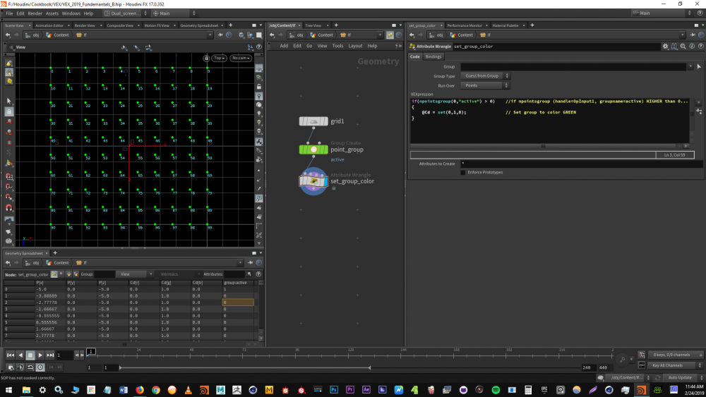
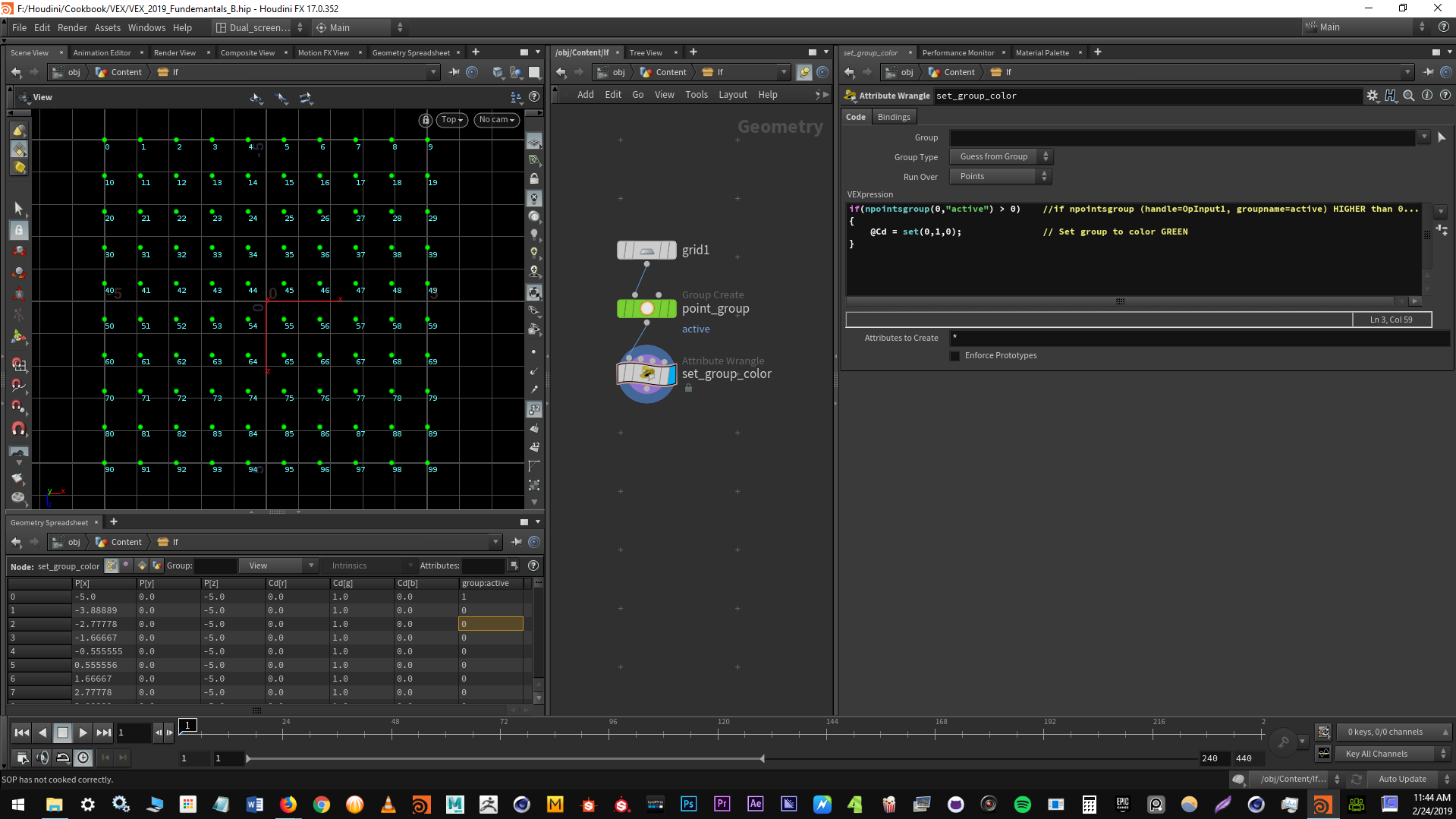
Each face has been inset, the same as if you had done this without the loop, because we've set the iterations to 1. Every scenario is different, so every time you start writing a loop, it's important to consider what type of loop is best. Maybe in one situation, you just want to use what is most convenient, but if you are processing large amounts of data, then performance might be critical. If a variable containing the element at the given index is defined during every iteration of the for loop, then it turns out that using a simple foreach loop takes the exact same amount of time. This is because IDL internally does the exact same thing in a foreach loop. Example on how to create primitive group and set condition to exclude selected geometry based on matching strings in geometry path attribute.
We've cretated 3attributeson points rampy, rampx, rampz. We can now double check that in the geometry spreadsheet tab. Visualise the attribute by dropping down thevisualise node. To be able to process each piece of the input geometry individually we are going to use For Each Loops which allows us to run the same chain of nodes multiple times. Following examples will demonstrate how to create attributes for each element based on primitive connectivity – in our case derived from 3D connected pieces, uvs or groups. Like any python expression you need to return your result.
So any string we return that contains vex code will get executed by this parameter. This loop repeats itself as long as the condition is true. In this case generates a point in world zero position, one hundred times. This wrangle SOP doesn't have any input and must be set to Detail mode as there are initially no points or primitives to run over. It seems like they've extended the support for arrays in H14, which makes it now possible to use them as geometry attributes.
In the previous versions I guess that there was no real point in creating arrays in VOP since you couldn't pass them downstream with the geometry data. If a node's inputs are changed - the data coming in through an input connection or a parameter is changed - it needs to reevaluate. Look for processes, nodes or calls that re-evalute over again and produce the same result.
A VEX loop's iterations runs in serial - each iteration has to finish before the next can start. All we need to do is move the nodes step1 and step2 in a Solver SOP. The Solver SOP will fetch the geometry only at the frame specified in the parameter Start Frame . For all the subsequent frames, the Solver will use the result of the previous iteration. I generally use detail attributes to store values that exist for the whole object.


No comments:
Post a Comment
Note: Only a member of this blog may post a comment.